The Clock Jobber's Handybook
By Paul N. Hasluck
Brought to you by:
Tick Tock Productions ™
The
CLOCK JOBBER'S HANDYBOOK.
PENDULUMS
THE CONTROLLERS.
CHAPTER V
EXAMINING AND CLEANING A 8-DAY CLOCK
That part of the mechanism that regulates the number of blows to be struck on the bell may be out of order, and worn in some parts. The rack, which must be considered as the segment of a wheel, should have its first tooth a little longer than the others, so that the other teeth will not grate on the point of the rack catch, and make a disagreeable noise when the clock warns before striking. The " tumbler," or gathering pallet, that works into the teeth of the rack, may be split or worn out. The figure 6 is a good model to follow in making a new one. It is necessary to cause the tumbler to lift a little more than one tooth, and let the rack fall back again, to insure that one will always be lifted. If such were not the case the clock would strike irregularly, and would also be liable sometimes to strike on continuously till it ran down. If the striking part be locked by the tail of the tumbler catching on a pin in the rack, the tail of the tumbler should be of such a shape that will best allow the rack to fall back when the clock warns for striking the next hour. Of course the acting faces must be perfectly smooth and well polished.
A guard pin ought to be put in the frame, if one does not already exist, to prevent the rack from going farther back than is necessary to strike twelve. Sometimes, when the striking part happens to run down first, the rack-arm rides on the snail on the hour wheel. The teeth of the rack are then, in some instances, allowed to go out of reach of the tumbler. In this case, when the clock is wound up, of course it will continue striking either till it runs down, or the weight is taken off, or the rack again put in action. It is necessary for the rack-arm to be made so that it will ride on the snail easily, because if the striking part, from any cause, should be stopped and the other part going, the clock would stop altogether between the hours of XII. and I. Therefore, put a guard pin, as already recommended. The teeth of the rack may require dressing up in some cases, and to allow this to be done the rack may be stretched a little at the stem, with a smooth-faced hammer, on a smooth anvil. If it wants much stretching, take the pene of the hammer and strike on the back, with the front lying on the smooth anvil. The point of the rack catch may be much worn, and when dressing up it will be safe to keep to the original shape or angle. The point of the rack catch is always broader than the rack, and the mark worn in it will be about the middle of the thickness; so enough will be left to show what the original shape was.
The striking train is generally examined in a less critical manner before taking to pieces; it is seldom so defective as to be likely to fail in striking; there being no resistance for the striking weight to overcome except the tension of the hammer tail-spring and rack-spring, and the inertia of the train wheels. Should it be thought necessary to be more careful, the course of procedure would be exactly similar to that described for the going train. The examination of the dial work is usually left until the clock is put together, as any errors can be easily altered, without in any way interfering with the rest of the clock. The plates may now be carefully wiped with a clean duster, a leather strip passed through the holes, and the wheels, pinions, and other parts brushed clean, ready for putting together.
In putting together, commence by screwing on the hammer spring and the cock. The cock is put on in order to allow the pivots to go through the holes until the shoulders rest on the plates, as the wheels do not fall about so much then as they otherwise would, and also to prevent the back plate being scratched by the work-board. Place the lower edge of the plate towards you, and put the wheels, &c., in their proper places in the following order: Centre wheel, third wheel, two great wheels, hammer, pin-wheel, escape-wheel, gathering-pallet wheel, warning-wheel, and last, the fly. Take care to have the catgut lines running the right sides of the pillars. If there is an arbor for a " strike or silent" arrangement, remember now to put it in, or it may necessitate taking the clock all to pieces when nearly finished.
When these parts are in their proper position, carefully put on the top plate, and, pressing it moderately tight, guide the pivots into their respective holes, starting from the lower part of the frame. It is sometimes a great assistance to put the point of an examining pin into the hole of the lower pillar, when the top plate is on sufficiently far, as you have only then to attend to the top part. For the clock to look well when finished, there must be no finger marks upon any part; to avoid which, hold the plates with a clean duster when putting together, and keep all the parts as bright as possible. When each pivot is in its place, and the top plate resting fairly on the shoulders of the pillars, pin up with the examining pins, and test the correctness of the relative positions of the wheels. There cannot easily be any mistake made with the " going " train, but it is advisable just to press round the great wheel a turn or so, and see that all runs freely.
The wheels of the striking train require to be placed in certain arbitrary positions in regard to each other, the great wheel and fly excepted. The first position to be tested is that existing between the pin-wheel and the gathering pallet pinion. In order to do this, put on temporarily the rack, rack-spring, hook, and gathering-pallet. Let the rack-hook hold the rack gathered up, with the exception of one tooth, and move round the pin-wheel very slowly until the hammer tail just drops off; at that instant the tail of the gathering-pallet should have about J in. from the pin in the rack which stops the striking. If there is an excess of this, or if the hammer tail is resting on a pin, the top plate must be slightly raised, and the pin-wheel moved a tooth further on in the pinion until it is as near the required position as possible.
The reason for making the striking train cease running, as soon as can safely be done after the hammer falls, is, that there may be as much run as possible before it has to raise the hammer, and overcome the tension of the hammer-spring. Never leave the hammer tail " on the rise "—that is, resting on one of the pins of the pin-wheel—when finished striking. Having adjusted this, see that " the run " of the warning wheel is right. Put on the lifter marked C, Fig. 25, and gradually raise it till the rack-hook liberates the train, and " warns." The distance the warning pin should run is half a turn, so that immediately before it "warns" it should be diametrically opposite the piece on the detent, against which it is stopped, until the lifter falls and the clock strikes. See that the warning pin catches fairly on the stop-piece of the detent; if it does not, it is because the rack-hook is raised either too soon or too late by the detent, and alter as may be necessary. When the train is quite correct, remove the rack, &c., and pin up the plates finally with good-shaped pins.
Nothing betrays a careless or incompetent workman sooner than the pins he uses in his work, and the manner in which they are put in. It matters little what care may be bestowed upon repairing and cleaning if the clock is badly pinned up, for no certainty of performance can be expected in such a case. Therefore make a properly-shaped pin, neither too thorny nor too straight, but gradually tapering, round and smooth, and well fitting the hole it is intended to occupy; then drive it in tight, and cut off at an equal length each side of the hole.
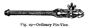
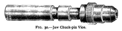
Almost the first thing in practical horology is to learn how to make pins. Take a piece of hard wood, about five-eighths of an inch square and an inch and a quarter long, flat and smooth on all sides and both ends. Having secured it in the bench vice, with an ordinary graver cut longitudinally on the top of the wood, and parallel with the jaws of the vice, four or five V-shaped grooves about equally distant; the first one about 5/8 in. deep, and the rest shallower to the last one, which is very faint. Then take a pin-vice, a hollow one is preferable (see Fig. 29 and Fig. 30), and put in a long piece of iron wire; let it project at least an inch beyond the jaws; lay it in the deepest groove. With a file press on the wire, giving the vice a twisting motion with the thumb and forefinger of the left hand rapidly towards you, and pushing the file from you with your right hand. Reverse the motion of the fingers of the left hand, at the same time drawing the file towards you, being careful in this motion to rest the file only sufficiently to keep the wire in the groove. Repeat these processes until the wire has been filed to a gradually tapering point. Then, with a finer-cut file in a shallower groove, make the pin smoother, and, finally, take a still shallower groove and with a burnisher remove all the file marks, leaving the pin perfectly round and bright.
_____________________________________________________________________________
Learn clock repair with these DVD courses! Course manuals are included.
Watch, study and learn antique clock repair through DVD course instruction using actual live repairs!!
Clock Repair 1 & 2 Advanced Clock Repair PRO advanced clock repair
Clockmaker Watchmaker Lathe Basics Clockmaker Watchmaker Lathe Projects Clock Case Repair & Restoration Wooden Works Movement Repair
© Copyright 2001-2009 by Tick Tock Productions © Copyright 2001-2009 by John Tope All rights reserved.
Back to clock information page.
Hasluck, Paul N. The Clock Jobber’s Handybook. London: Crosby Lockwood and Son, 1889.
This and the following pages are excerpts from the book.