The Clock Jobber's Handybook
By Paul N. Hasluck
Brought to you by:
Tick Tock Productions ™
The
CLOCK JOBBER'S HANDYBOOK.
PENDULUMS
THE CONTROLLERS.
In planning a clock the pendulum claims first attention. Though
apparently a simple adjunct to a clock, the pendulum is in reality the
most important part of its construction, for the value of the clock as a
reliable timekeeping machine depends upon its free and regular movement.
The function of the pendulum is to control the velocity of the going train
with uniformity, and at a fixed rate, and it must be uninfluenced by the
train except in receiving a sufficient amount of impulse to keep up its
vibrations. Before commencing
to make a pendulum for a new clock, or to supply the place of a lost one,
it is very desirable to know something of the laws and properties of
pendulums.
The
simplest form of pendulum may be described as consisting of a weight
suspended by some flexible substance and free to swing when moved on one
side and then released. The
power which operates upon the pendulum is gravity, and the velocity it
attains is proportional to the height fallen, notwithstanding the fact
that the curve which the weight describes offers a resistance tending to
neutralise in some degree the gravitating force. The effective force of
gravity in producing the motion of the pendulum depends upon the position
of the weight in relation to the vertical. The greater the distance the
pendulum is moved from the vertical, the greater is the impelling force of
gravity. From this, two important facts may be learnt. One, that a
pendulum of a given length moves quicker in proportion to the distance it
swings, therefore it will move through a large
arc in the same time as a short one, and vice versa. In other words, when
the extent of vibration is very little, gravity exercises but little force
; but, as the vibration increases in amount, the force of gravity becomes
proportionately greater, causing the pendulum to move through a large arc
in the same time as through a short one.
In one instance it moves through a large space quickly, in the other
through a small space slowly, the time occupied being the same in both
cases. Strictly speaking, this is not true of a pendulum moving in a
circular arc, but it is so with a pendulum moving in what is known as a
cycloidal curve. A cycloid is
a curve of the shape traced out by a point in the rim of a circle rolling
upon a straight plane. This cycloidal curve corresponds for a certain
distance from the vertical with the circle. The
vibrations of pendulums are generally of small extent, and any pendulum
suspended by a spring never moves exactly in a circle. For these reasons
it has been found sufficiently correct for all ordinary purposes to reckon
that in pendulums of the same length unequal arcs are equal timed. This
peculiar property of the pendulum is called its isochronism, and the
difference between the time of vibration of a simple pendulum influenced
only by gravity, swinging in a circular arc, and one of the same length
moving in a cycloidal curve is known as the circular error.
Another important fact is, that
theoretically the vibrations of a pendulum are not altered by the weight
or material of the bob, unless it is so light as to suffer from the
resistance of the air. Consequently a pendulum of a given length may have
a bob of any material either light or heavy, and it will vibrate in the
same time. In practice, it is found that from various causes weight, and,
therefore, material, does make some difference in the time of vibration of
a pendulum. There is another cause which disturbs the uniform rate of
vibrations in a pendulum which must be just noticed, that is, the varying
density of the atmosphere. The effect of this is known as the barometric
error, and to reduce it as much as possible, the " bob " must be
made as small as it can be for its weight, and also of such a shape as
will pass through the air with the least resistance and without any
tendency to "wobble." In pendulums swinging 2.5 derees each side
of zero, the barometric error is stated to be exactly compensated by the
circular error.
The above reasoning shows that the
velocity which the pendulum attains, or its time of vibration, is
proportional to the height fallen. The circumference of a circle may be
considered to be 3.1416 times its diameter, and it is proved that the time
of vibration of a simple pendulum will be 3.1416 x the time required for a
body to fall vertically a distance equal to half the length of the
pendulum. It being well known
that the times of falling from different heights are proportionate to the
square roots of the distances fallen, it follows that the time of
vibration of a pendulum varies as the square root of its length. Perhaps
this will be better understood by stating that a pendulum i ft. long would
vibrate four times during one swing of a pendulum 2 ft. long, and nine
times during one swing of a pendulum 3 ft. long. This
reasoning applies properly to what is termed a simple pendulum, that is,
one in which the rod is supposed to be without weight, the entire weight
of the pendulum being at one point at the extremity. Such a pendulum
cannot actually be made, and therefore the application of the rule has to
be considered in relation to pendulums as they are usually met with.
Pendulums commonly in use have the rods made either of wood or metal,
sufficiently large and strong to support the heavy bob at the bottom.
The principle upon which compensated
pendulums are constructed may be briefly stated as a proper application of
the expansion of metals. The most simple arrangement is that in which the
"bob" expands upwards in such proportion to the lengthening of
the pendulum rod that the centre of oscillation is always kept the same
distance from the point of suspension. The cheapest and most simple form
of compensated pendulum for vibrating seconds is made of yellow deal. It
should be well-seasoned and straight, not sappy, nor of strong grain full
of turpentine. The rod should be about 46 in. long, and f in. in diameter,
and either well varnished with good spirit varnish or painted and gilt.
The bob should be of lead, about 14 in. high, resting on the regulating
nut at the bottom. The mounts at the top and bottom of the rod, as also
that which receives the crutch-pin, are made of brass.
A clock or any other timekeeper cannot
be easily regulated to keep mean time, because the mechanical adjustment
of the regulator is not sufficiently fine to allow of it. As an example,
suppose we have a pendulum 40 in. in length vibrating some 3,600 times per
hour, by altering the length only 1/1000 part of its length, about one
twenty-fifth part of an inch, it will cause a variation of one minute per
day. These figures are only approximate, but quite near enough for the
argument; e.g., for convenience in calculating taking 40 in. for length of
pendulum. The exact length of one to vibrate 3,600 times an hour in London
is 39.1393 in., whilst at the equator a pendulum 39.017 beats seconds. A
clock going within seven minutes per week of mean time would be considered
very badly regulated, and yet the alteration of 4/100 of an inch in the
length of a seconds pendulum, or 1/100 of an inch in a half- seconds
pendulum, will cause seven minutes a week difference in the rate.
Coming to the mechanical adjustment,
we find that the pendulum bob is raised and lowered by a nut on a screw,
having perhaps some 50 threads per inch, so that one turn of the nut will
make, say, 3.5 minutes per week difference in the rate of the clock. We
can, however, divide the nut into, say, one hundred parts at its
periphery, and then each division will represent a gain or loss of 18
seconds per month of 30 days, or about 31 minutes a year — not a very
close rate after all. However, in practice the final adjustment is made by
sliding a small weight on the rod. By a consideration of the above
calculation, it will be easy to understand how minute must be the
alteration in the regulation of a clock to cause it to gain or lose only,
say, half a minute in 24 hours.
The gridiron pendulum of Harrison's is
now almost entirely disused on account of the expense and trouble of
making it, and also of its appearance. It consists of four pairs of brass
and steel rods, and the steel rod which supports the bob. The mercurial
pendulum, though very simple in construction, is as near perfection as can
be desired, the only objection being its great expense. There are two
forms in use; in one the mercury is contained in a straight glass vessel
standing in a stirrup at the bottom of the rod, and in the other the
mercury is in a cast-iron jar, into which the end of the rod dips. The
great feature of the mercurial pendulum is the ease and accuracy with
which the compensation can be tested and adjusted by simply taking away or
adding mercury, as may be found necessary.
Whichever form of pendulum is
selected, whether plain or compensated, it is of the greatest importance
that its suspension should be well made, and quite free from any looseness
when the pendulum is set in motion. When the pendulum is long and the bob
heavy, it is always desirable to suspend it from the back of the case, and
not from a cock attached to the movement itself. On page 63, parts of such
a suspension are illustrated.
It is of importance that the
underneath of the "chops" which clip the spring should be quite
square, and not rounded as they often are, because the spring will be
liable to impart a twist to the pendulum at every vibration, if not
perfectly free to bend in the correct manner. The bend of the pendulum
spring should be exactly opposite the centre of the pallet-arbor pivot, in
order that the up and down friction of the crutch may be as little as
possible.
The method of making a pendulum spring
for an English clock is to soften a piece of wide watch main-spring, and
then " draw it down " between two files — that is, pinch the
spring in the vice by its lower end, and then tightly grip it between two
files and draw them along its whole length. This is rather a troublesome
and unsatisfactory plan, and it is much better to buy prepared pendulum
spring, which can be obtained at a very moderate price, of the spring
makers.
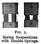
The accompanying illustrations show a useful form of spring suspensions having double springs, which greatly control any tendency of the pendulum to wobble.
The lighter the pendulum bob, the
thinner the spring should be. The suspension springs are very often left
too thick; or much too long and narrow. Generally the suspension spring
should be as thin as possible, provided it is not so slight as to bend
abruptly close to the chops or unsafe to support the pendulum weight.
Learn clock repair with these DVD courses! Course manuals are included.
Watch, study and learn antique clock repair through DVD course instruction using actual live repairs!!
Clock Repair 1 & 2 Advanced Clock Repair PRO advanced clock repair
Clockmaker Watchmaker Lathe Basics Clockmaker Watchmaker Lathe Projects Clock Case Repair & Restoration Wooden Works Movement Repair
© Copyright 2001-2009 by Tick Tock Productions © Copyright 2001-2009 by John Tope All rights reserved.
Back to clock information page.
Hasluck, Paul N. The Clock Jobber’s Handybook. London: Crosby Lockwood and Son, 1889.
This and the following pages are excerpts from the book.